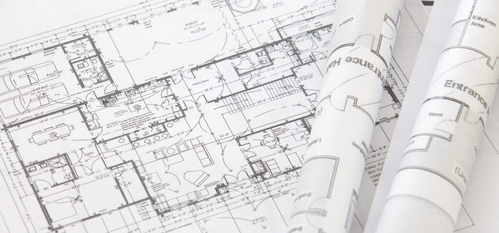
Standard scale specifications for printed blueprints and construction drawings are essential for ensuring that drawings are understood correctly and used appropriately in the field.

Standard scale printed blueprints: Our standard scale printed blueprints service delivers expert results.
Standard Scale Printed Blueprints: What is Scale on Blueprints?
Blueprint scale defines the relationship between dimensions on the drawing and actual dimensions in the field. A drawing scaled at 1/4″ = 1′ means that 1/4 inch on the drawing represents 1 foot of actual construction. Scale enables architects and engineers to represent large buildings and sites on manageable paper or screen sizes while maintaining proportional accuracy.
Common Architectural Scales
1/8″ = 1′ is commonly used for overall building plans, site plans with large areas, and space planning drawings where detailed dimensions are provided in schedules. This scale provides overview perspective suitable for understanding overall layout.
1/4″ = 1′ is the most common scale for construction drawings including floor plans, elevations, and section views. This scale provides adequate detail for construction while fitting drawings on standard sheet sizes. Most construction drawings at this scale are easily understood in the field.
3/8″ = 1′ and 1/2″ = 1′ scales are used when more detail is needed, such as wall sections, mechanical details, and assemblies where precise dimensions and connections must be clearly shown. These larger scales make details easier to understand in the field.
3/4″ = 1′ and 1″ = 1′ scales are used for very detailed drawings including door and window details, cabinet details, and connection details. These scales show maximum detail suitable for understanding precise construction methods.
Full Scale (1:1) is used for patterns, templates, and objects small enough to draw at actual size. Full scale drawings are rarely used in construction because most buildings are too large.
Standard scale printed blueprints: Engineering and Site Plan Scales
Civil engineering and site plans often use different scales than architectural drawings. Common site plan scales include 1″ = 10′, 1″ = 20′, 1″ = 30′, 1″ = 50′, and 1″ = 100′. These scales represent larger areas suitable for site layout, utilities, and grading plans.
Engineering plans may use metric scales such as 1:100, 1:200, or 1:500 depending on project size and regional standards.
Why Scale Matters
Correct scale ensures that construction professionals can accurately interpret drawings and translate them to field dimensions. Scaled drawings prevent misinterpretation and costly errors. When drawings are not clearly scaled, confusion and errors are common.
Scale must be clearly indicated on every drawing sheet. Title blocks typically include scale notation. Multiple scales on a single sheet require clear indication of which scale applies to which views.
Scaled Drawings vs. CAD Dimensions
Modern construction relies on written dimensions more than scaled measurements. Dimensions on the drawing provide precise measurements that supersede scaled dimensions. However, scaled dimensions remain important as a check and for situations where specific dimensions aren’t provided.
Construction professionals should never scale drawings using rulers because minor printing variations distort scaled measurements. Always use written dimensions when available.
Printed Scale Considerations
When blueprints are printed, scaling must be maintained accurately. Printing at incorrect scale (such as “fit to page” printing) renders drawings useless because dimensions are no longer correct. Reprographic professionals maintain precise scale during printing through proper software settings and calibration.
Shrinkage or expansion of blueprint media can slightly distort scale. Tyvek and polyester media are more stable than paper, maintaining scale accuracy better over time.
Digital vs. Printed Scale
Digital CAD files include scale information that is maintained when printed correctly. When CAD drawings are printed, scale must be explicitly set to maintain accuracy. Common printing errors include “scale to fit” which distorts scale, or incorrect scale entry which results in over- or under-sized prints.
PDF documents can embed scale information, but viewers must be aware that PDF scale may be distorted if the PDF is created from incorrectly-scaled prints.
Metric vs. Imperial Scales
United States construction primarily uses imperial scales (fractions of inches per feet). Metric scales use ratios such as 1:50, 1:100, 1:200. Understanding and correctly applying the appropriate scale system prevents costly errors.
International projects or firms working internationally must clearly indicate whether drawings use imperial or metric scales.
Scale Bars on Drawings
Professional drawings often include scale bars (graphical representations of known distances) to provide scale reference independent of text notation. Scale bars remain accurate even if the drawing is resized or scanned, making them valuable for verification.
Best Practices for Blueprint Scaling
More standard scale printed blueprints content.
Always verify that drawings are printed at correct scale before distributing to field personnel. Use scale verification methods such as measuring a known dimension and verifying it matches the scale. Clearly indicate scale on all drawing sheets. Use multiple scales on sheet sets only when necessary and clearly identify which scale applies to each view.
For information on industry printing standards and best practices, the Printing United Alliance provides valuable resources for professional print quality and accuracy.
When blueprints are printed, scale accuracy is essential for construction professionals to correctly interpret and implement drawings. Clear scale indication, proper printing, and accurate scale maintenance prevent costly field errors. See our large format printing or contact us. Resources at printing.org.